Reggaebox
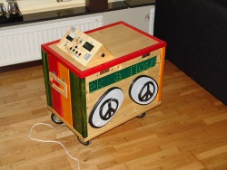
Reggaebox Mk II - Portable Music System, Roskilde Festival 2009. VMUSIC2-based portable music system with dot-matrix ID3 display running on PIC16F676
Contents |
[edit] Participants
- @STG - Coordinator, funding
- Jenx - Supersolderer and construction
- Lawgom - Last minute soldering help
[edit] Coverage (videos, pictures, articles)
- Blog entry (video, pictures): In the park @devsound
[edit] Project status
This project was completed, and is added to the wiki only as a historical reference for the current project:
Dot-matrix entertainment system
[edit] Introduction
The goal was to design, build and program a music box for the 2009 Roskilde Festival in Denmark, in the five days leading up to the festival. All features except the remote control were implemented. Additionally, the control panel was fitted with a flashing power indicator, a battery voltage guage and a temperature sensor. An aux. audio input jack was also installed in the USB hatch.
This project shows how to interface a simple Microchip 8-bit PIC microcontroller (PIC16F676) with an FTDI VINCULUM VMUSIC2 module without the need for a hardware UART/FIFO or SPI interface. Available are schematics and code for a 50x7 dot-matrix LED display.
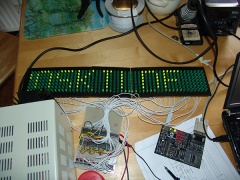
[edit] The dot matrix display
A fun and simple project in it self, and one that could be adapted for a variety of purposes.
The controller is designed to be connected to another microcontroller - BUT - it does communicate with standard 9600bps 8N1 format and as such it can be adapted to be connected to a PC using for example a MAX232 chip or an FTDI FT232R usb to ttl serial cable without any significant effort. The FTDI cable has the advantage that it will also provide 5V power for the display directly from the computers USB port. Some code changes will be required however, as we are currently deviating slightly from regular communications. This deviation consists in lowering the serial line just after the last stop-bit of a packet until it is time to send the next packet. The line is then raised for a predefined delay before sending the packet using regular communication. This allows the display microcontroller just enough time to complete it's current task, detect that a transmission is pending and enter receive-mode (an endless loop waiting for a start-bit). This functionality can easily be replaced by RTS/CTS-signalling.
[edit] Credits
Scrolling text display - we used this as a template for the display hardware.
[edit] Features initially planned
- Reggae theme
- Slightly weather resistant
- Festival-survival-strong construction
- Car battery power source
- Built-in MP3 audio system
- ID3-tag presentation using a LED-matrix display
- Some form of control panel
- Remote control (not implemented, ran out of time)
[edit] Cost
Roughly 2500:- (SEK), €250 or $300. We scavenged many of the parts though: some of the wood, the wheels, experiment boards, all wires and cables except the audio signal cable, the power amplifier, speakers, battery, thermometer and volt guage. The most expensive parts were the LEDs, the VMUSIC2 and the switch regulator which stood for roughly 1/3 of the cost. Wood, paint and other construction materials - roughly 1/3. The final 1/3 went to assorted electronics, control panel buttons, spare parts, etc...
[edit] Future plans
Pre-amplifier (the built in mp3 player is unable to "max out" the power amp or speakers) Remote control Various software improvements Jamaican style straw roof/umbrella (goes well with the theme and allows use when it rains) Motorised joystick-controlled carriage Large full-color dot-matrix display for gaming
[edit] Main board functional description
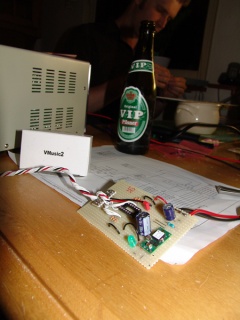
The microcontroller on the main board communicates with the VMUSIC2 module using software-based serial communication. Hardware flow control allows the software to halt incoming transmissions while busy processing other information. This is "necessary" for code simplicity when there is no FIFO (buffer in a hardware UART) available. The original idea was to communicate using SPI but this was abandoned due to problems with the unit, see below.
The VMUSIC2 module performs all playback and ID3 tag decoding. Once a song starts playing - the decoded ID3 tag information is sent to the CPU, which constructs and sends a data packet to the display controller.
The main board also detects keypresses and commands the VMUSIC2 and display module accordingly.
Initially we had some problems with the VMUSIC2 module:
- The module did not recognize ANY of my USB sticks
- The module did not act according to the manual
- SPI mode was not functional (despite strapping for SPI, the module remained in UART mode)
- In UART mode, the RTS pin was always asserted - even when no data was available
Once we got basic UART communication going it turns out the firmware was VERY old! I tried to update the module using a MAX232 circuit but managed to corrupt the firmware instead. Given the shortage of time we decided to purchase an FT232R cable and construct a 2.54mm -> 2.00mm pitch adapter for the VMUSIC2 module. After the firmware was updated we had much more luck with my USB sticks, and the module started to behave as specified. We have not gotten around to trying out SPI mode or RTS pin functionality with the new firmware. Might be worth noting that the reason we were unable to update the firmware using a MAX232 was that programming requires the CTS and RTS pins to be hooked up. We only connected the TXD and RXD pins.
Also located on the main board is the power supply. We chose to go with a switched power supply due to the higher efficiency of these regulators in combination with the fact that this is a battery powered application. We were unable to find a regulator in-stock that was suitable for such low current applications so we went with one rated at 6A. This regulator gives us terrible efficiency at the roughly 200-600mA (depending on audio) that the system requires and it's quite possible that we would have been better off using a 7805. This kinda stuff happens when you're short on time and working around the clock.
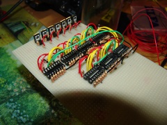
[edit] Display controller functional description
The display module receives a packet on a serial line and stores it in RAM. The packet contains an "animation" parameter, the length of the text and the actual text in ASCII format. When the packet has been received in it's entirety, the program enters into an infinite cycle of "refreshing" the display, row by row.
For each row on the display it translates current parameters (text, animation state, font data) into a stream of bits representing the pixels (on/off) for the row currently being processed. These bits are fed into the shift registers (XDRV & 74HC595) one by one by writing a bit to the data line followed by a pulse on the clock line.
The shift registers do not change their outputs while this is being done because they are of the latched type. This means they require a pulse on the latch line to "copy" their internal data to their outputs.
When the shift registers are fully loaded all row drivers are temporarily disabled by setting row 7 (the eigth row, which is not connected), the shift registers are then latched and the driver (YDRV) for the current row is enabled. At this point all of the desired LEDs on this row are lit.
The microcontroller then moves on to the next row and repeats the same cycle until it reaches row 6 (seventh row) after which it starts over with row 0. This happens hundreds of times each second - hence the flickering is not noticeable.
The line decoder (74LS138) is used only to limit the number of pins required on the CPU and simplify the code. It allows me to simply output the number of the row I want enabled instead of controlling individual pins manually. For example, outputting 3 (binary 011) on port A (RA0-RA2) will make the decoder enable it's /Y3 line.
[edit] The technical stuff
The schematics shows a display that has 64 columns but in practice we only managed to fit 50. Simply removing or repeating more XDRV (see schematic) circuits will allow you to construct a display with any number of columns you choose, given that the source code "#define"s are modified accordingly. Although the provided code does not support it you could also, in theory, add more row drivers by adding more YDRV circuits and additional 3-8 decoders - hooking up their enable pins to the remaining microcontroller outputs. Somewhere along the road you will need a faster CPU though. 64x7 is near what this processor is capable of displaying (using my method of font storage) without significant flickering. Memory is also a consideration.
Remember that the 120R resistors on the XDRV circuit are suitable for 2.1V forward drop LEDs. Make sure you match the resistors to whatever LEDs you decide to use. Google "led calculator" if you need help determining the correct resistance. Note that even if your LEDs can handle higher currents, the 74HC595 can only safely deliver 25mA per output - do not use a resistor/LED combination that exceeds this limitation.
Source code is written for the CC5X compiler (freeware).
STG: How do we add source code to the wiki? For now, all downloads and the picture diary are available at the original project site